Transcript
00:03Welcome to connector products, optical ground wire down lead clamps installation video.
00:09We will review the installation of the banding down lead clamp version.
00:13This clamp is designed for use on optical ground wire and is used to guide the conductor
00:18down a structure to the splice box. It is purposely designed with a range to accept
00:23any number of conductors.
00:25Make sure you have all tools needed for the installation.
00:28In this case, a three quarter inch wrench or socket which can also be used with an impact
00:32drill. Confirm that you have the correct part number
00:35from connector products. The range that the down lead clamp accepts is
00:39both on the packaging and engraved on the top of the clamp.
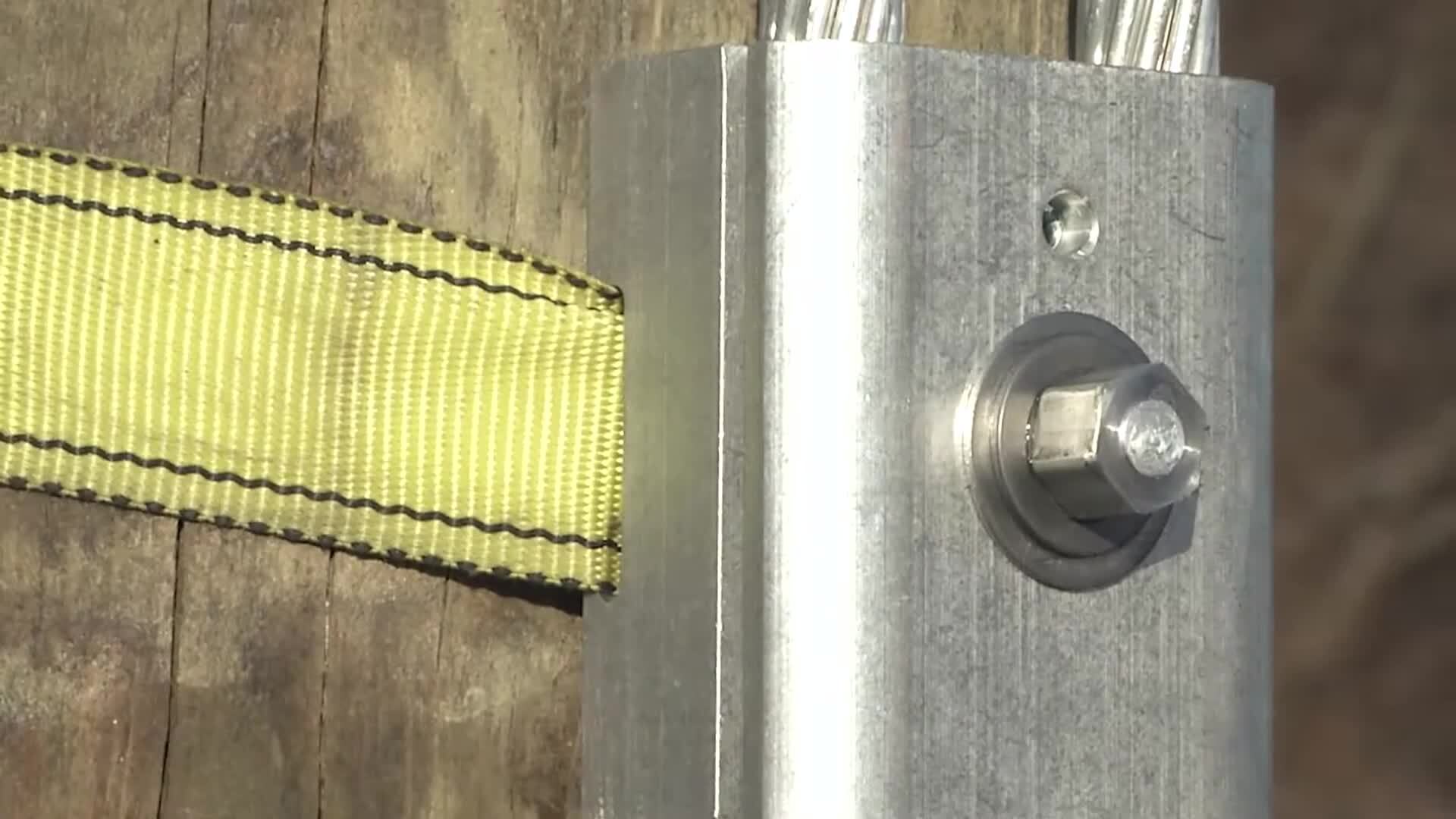
00:42Insert the band into the through holes provided within the down lead clamp position and tighten
00:47the band. According to the manufacturer's specifications,
00:51remove the top portion of the down lead clamp by removing the center bolt.
00:55Depending on the size of the OPGW connector being used.
00:59You may be able to simply lose in the bolt without removing it entirely seat the
01:03conductors in the grooves provided reinstall the top of the clamp and align the pin provided
01:08with the through hole on the top portion of the clamp begin to tighten the bolt by hand to
01:13ensure the conductor remains within the grooves of the clamp.
01:16Once the conductor is seated within the grooves of the clamp,
01:19you may fully tighten the bolt head.
01:21Once the top portion of the sheer head bolt shears off installation is complete.

CPI OPGW Down Lead Clamp
- private
- cpi